R61 trackpoint keyboard mod, Part 2
Part 2 of modding a trackpoint onto my crkbd keyboard.
In Part 1, I sourced the trackpoint module and reassembled it into a smaller footprint.
In this post I go over wiring the driver board to the keyboard controller, and spatially packaging everything onto my keyboard. Because I was figuring this out on the fly while also wrestling with my bootloader, I did not do things in a wise or efficient order at all. However, I have rearranged my process so that it is laid out in a more reasonable order here.
0. Prep your firmware
Your firmware should be ready before you solder so that you can actually plug your controller into a breadboard and see if the trackpoint works. (Since my QMK toolchain was broken for a hot second, I got impatient and did this step last. Please do not do as I did.)
Tips
- The side with the trackpoint mounted needs to be the master (cabled) side.
#define MASTER_RIGHTalso needs to be set inconfig.h. - It’s helpful to have debug settings on. If using
manna-harbourfirmware, you can changeMH_DEBUGtoyes. Also, here’s the general QMK debug settings guide. - Depending on how you mounted your module, you might need to change the
#define PS2_MOUSE_ROTATEorientation inconfig.h.
1. Figure out the spatial configuration
This section assumes you don’t want to have circuits sticking haphazardly out the sides of your keyboard. If that doesn’t apply to you, go wild.
Materials
- stripboard
- 100k resistor
- 4.7k resistors, 2x
- 2.2uF polarized capacitor; higher capacitance is also ok since this cap is just for smoothing, not timing
Spatial constraints
The trackpoint module needs to be mounted to something; a natural choice is to mount to the underside of the screen cover that comes with crkbd sandwich cases.
Due to the very tiny amount of space available on a crkbd, your configuration is going to be largely dependent on your components and your controller height off the board.
If your controller mount is very low profile (pins directly into sockets), you can probably sandwich the whole trackpoint mod right on top of the controller and skip a lot of steps I did.
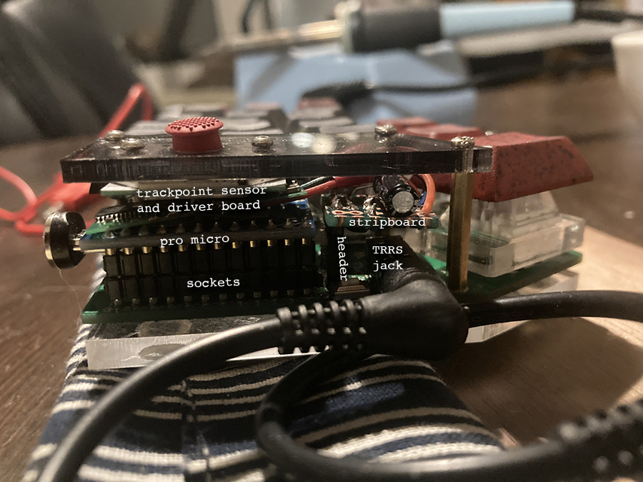
My controller has header pins which add about 4.5mm. I appreciate these, as it would have been much harder to fix my bootloader without long pins, but it does restrict space. I could only fit my additional components over the TRRS jack.
This also gets easier if you have access to surface mount components that fit between the holes on your stripboard. I only had big components, so I had to do some creative rearrangement to make it all fit.
Placing the stripboard
You will need a 5-column by 6-row piece of stripboard. If you don’t have a good saw and vise handy, you can use the score & snap method.
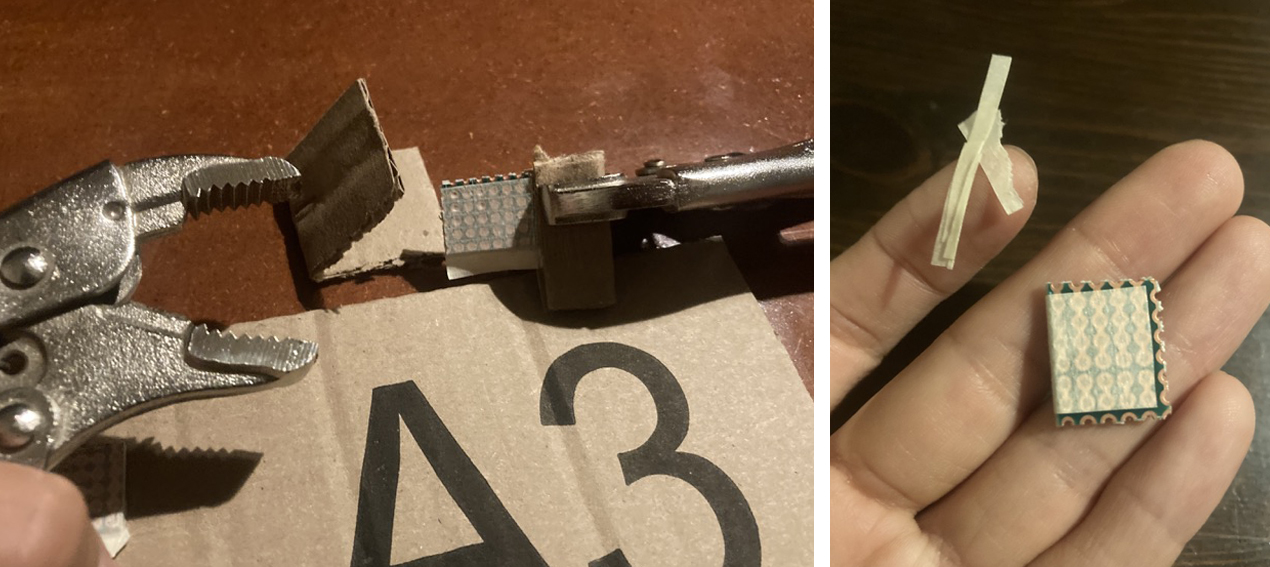
- Score the board on the adjacent row/column with a utility knife, razor, etc.
- Wrap something around the board to protect the traces from pliers. I used masking tape and cardboard.
- Use two pairs of pliers (locking pliers / vise grips are easiest) to flex back and forth until it snaps along the scored line.
Normally I don’t bother filing the snapped edges off stripboard, but in this particular case, I needed to file the snapped row/column almost all the way down to the edge to make it fit in my available space. You can use a small flat file or a piece of sandpaper.
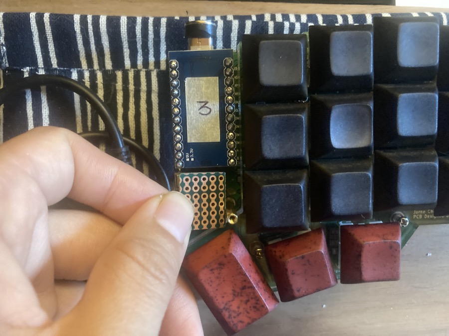
Note that I have no room to move the stripboard any further to the right because it’s already touching the brass standoff. This means that the header pins must be mounted on the right side of the stripboard, which constrains my wiring options.
Wiring
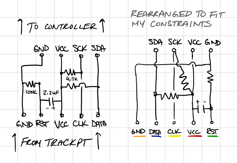
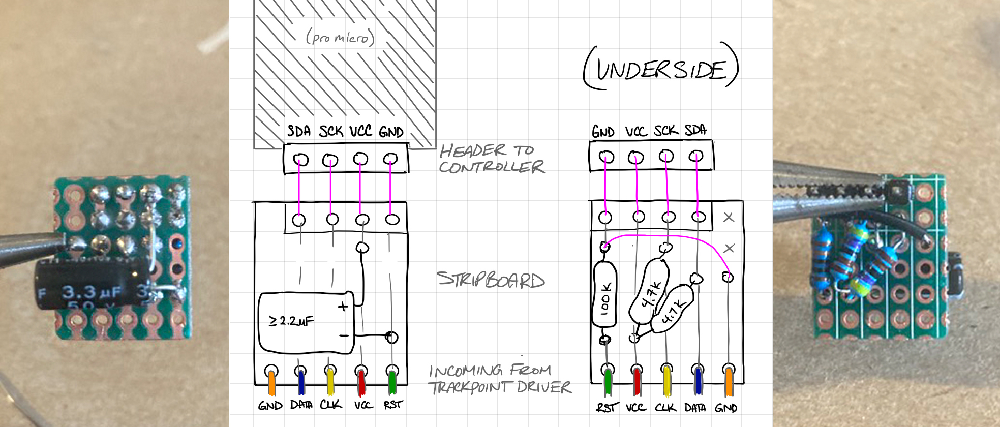
manna-harbour’s wiring diagram appears to assume that your stripboard fits on top of your Pro Micro. It will also be very difficult to fit the components in this particular configuration unless you have SMCs.
(top: from trackpoint; bottom: to keyboard controller)
| RST (green) | GND (orange) | VCC (red) | CLK (yellow) | DATA (blue) |
|---|---|---|---|---|
| 2.2uF(-) | 2.2uF(+) | |||
| 100k | 100k | |||
| 4.7k #1 | 4.7k #1 | |||
| 4.7k #2 | 4.7k #2 | |||
| GND | VCC | SCK | SDA |
I redrew this as a circuit diagram for more clarity.
Wiring with non-surface-mount components
I then rearranged components around on the stripboard until they fit compactly.
I needed to put my capacitor on top with its legs in adjacent columns, and all the resistors on the underside of the board. Note that my stripboard orientation is flipped so that it goes over the TRRS jack instead of over the Pro Micro.
2. Check your circuit
I highly recommend breadboarding your circuit before soldering to check that it’s correct. If your firmware works, then at this point you can actually plug into the header and check the trackpoint functionality.
If you simply wrap wires through stripboard holes, you will be able to do a basic continuity check, but you will not have a solid enough contact to correctly send data signals – you need either a soldered or breadboarded contact to send data.
Basic continuity check with multimeter
Ideally you would have also checked the module itself when harvesting it from the keyboard, but we can’t all think that far ahead.
I saw 4.4V on VCC and SDA, 3.4V on SCK, and 0.0V on GND, which seemed pretty reasonable.
I also confirmed that SDA (data) output voltage was changing in direct response to manipulation of the trackpoint, and not changing otherwise.
3. Make the mount
For this, I modified the acrylic screen cover that came with my crkbd case plates.
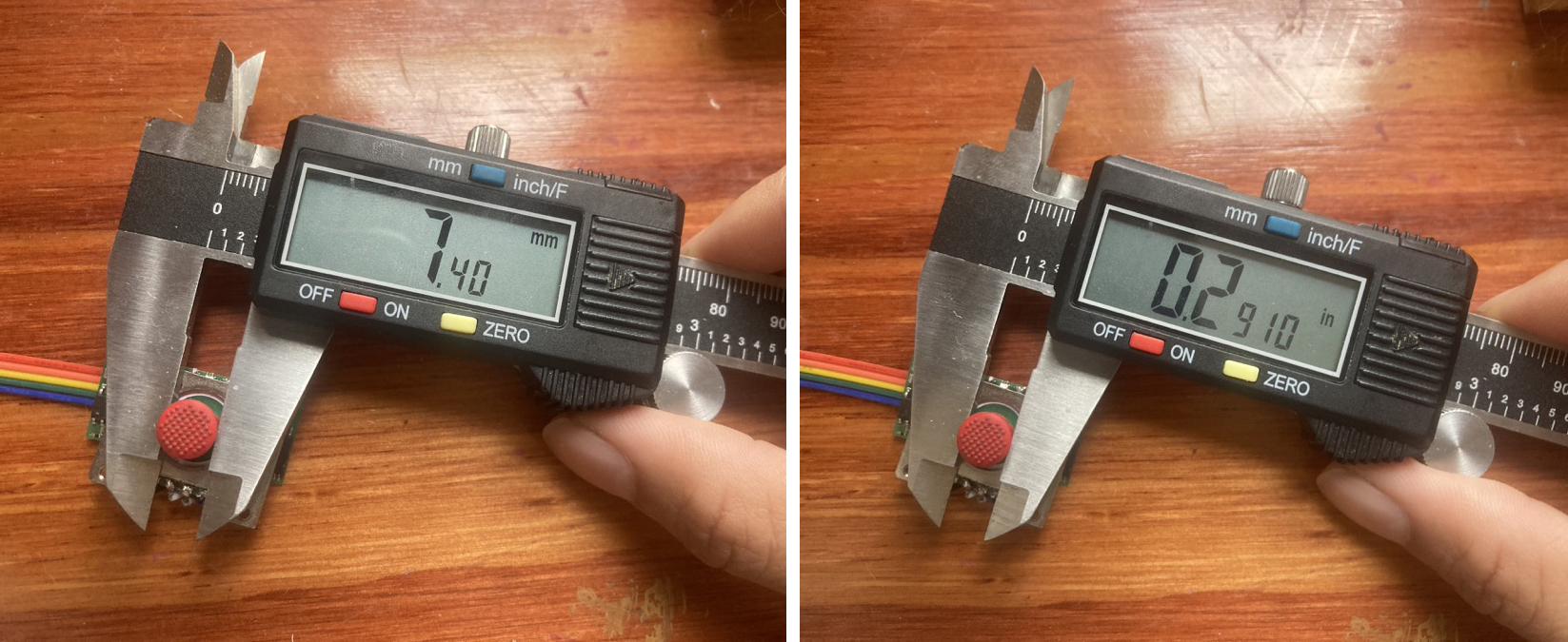
I first did the trackpoint hole (slip fit ~5/16”, but larger is ok) and then the two mounting holes (M2 screws, slip fit 5/64”).
I only have intermittent thirdhand access to a lasercutter and I’m good at precision work, so I did this by hand. If you want this to line up cleanly, then I really would not recommend making this mount without a lasercutter or at least a drill press, unless you have some precision machining experience as well as a caliper, center punch, and pilot bits on hand.
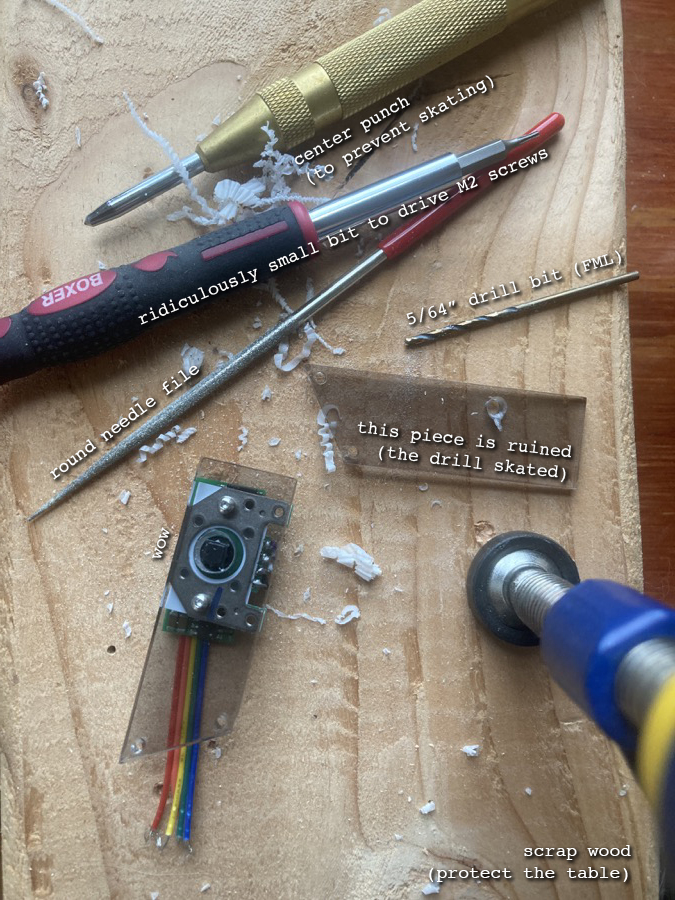
As you can see, I accidentally ruined the first piece by letting the bit skate, and nearly ruined the second piece because acrylic has a tendency to chip and shatter.
-
Line up the module under the acrylic and rough mark the hole center on two axes with a sharpie or paint pen.
-
Use a scriber or caliper tips to precision mark the actual XY center into the sharpie mark. I skipped this step and checked the true center by eye because I’m a badass and I was too tired to think, but in retrospect that was a stupid idea and I wouldn’t recommend skipping this step.
-
Check the placement at least three times, and then mark the center with a center punch.
-
For the trackpoint hole, you must first start and widen both sides with a pilot drill bit; a large drill bit is very likely to shatter the acrylic (ask me how I know). You may also need to clamp the piece down or at least brace it against rotary torque. For the M2 holes, going straight to the 5/64” bit is fine.
To relieve cantilever strain on the acrylic while downward force is being applied to the trackpoint, you should also add a standoff that supports it from the other side. It doesn’t need to be bolted down to anything, so precision is less important, but you should still at least center punch the mark you choose to prevent the bit from skating.
I’ll make a lasercutter file for this in the future when I’m less hosed.
Notes on trackpoint placement
I did this a bit hastily because I was impatient to get it working and I knew I was going to redo the acrylic covers in a darker or more opaque color soon anyways. My current placement is ok but is not the most ergonomic.
I would recommend aligning the trackpoint more with the home row. See manna-harbour’s and jorne’s build photos for examples of better placement.
You may also consider flipping it to face to the right so that it is closer to your hand, although I decided to make mine face left because I didn’t want to have the solder joints on the exposed side.
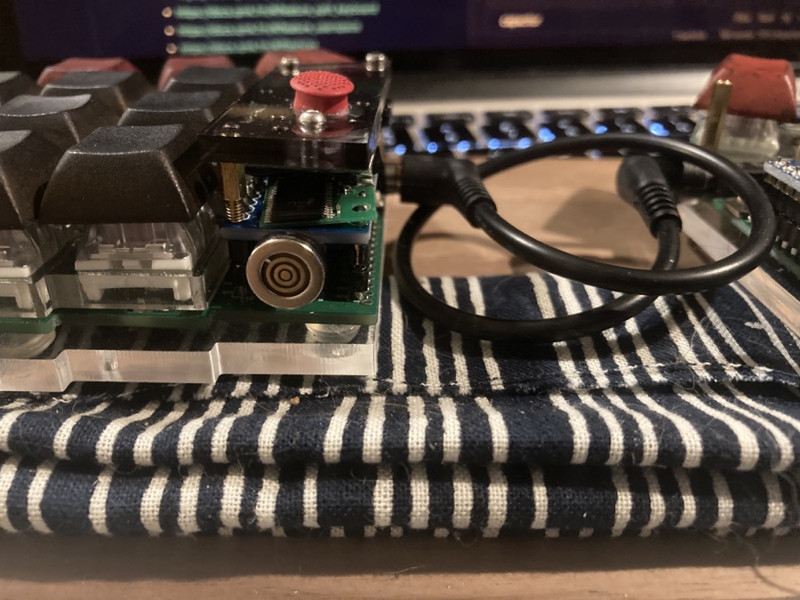
4. Assemble and enjoy!
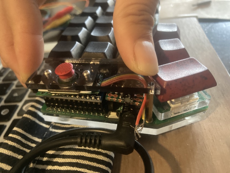
IT WORKS! Now I need to actually learn how to use QMK so I can port my custom keymap and tweak the PS2 mouse settings. Hooray!!!