Unbricking my Pro Micro
QMK is an extraordinarily versatile open source customizable firmware for input devices such as custom keyboards, mice, etc. Unfortunately, I did not get to do anything fun with QMK because I accidentally corrupted my firmware, so that’s what we’ll be talking about today.
In this post, I’ll go over my debugging process for getting a working firmware back onto a Pro Micro that wasn’t working as intended, and fixing its bootloader using an Arduino as an ISP programmer.
For context, I am an absolute firmware newb and have not done AVR programming before this, though I have interfaced with chips as blackboxes before such as with hobby electronics or breadboarding chips together.
This post is now fixed with some new information I learned on 2021-10-24. I highly recommend reading this newer post before re-flashing your bootloaders, if it turns out you need to do that.
Environment
- OSX 10.14.6
- Keyboard controllers: 5V Pro Micro, ATmega32u4 chip
- Keyboard board:
crkbd
My “legacy” OSX 10.13 appeared to have some compatibility issues with running QMK, so I waited until recently when I was willing to upgrade to 10.14 (I’ve been avoiding 10.15 for developer incompatibility reasons).
In the meantime, I’ve been tweaking my keymap with VIA, an extremely user friendly piece of software that doesn’t have as many features as QMK but still lets you do quite a bit of customization including basic Mod-Tap for multiplexing tapped and held keycodes.
So, I bricked my controller
I tried reflashing a default firmware build onto my controllers with QMK Toolbox and instantaneously bricked the right-hand side. While the left Pro Micro was still flashable, the right could not be flashed over USB and also stopped functioning as a keyboard.
Debug checklist
- What functions still appear to work? (Typing, screen, underglow LEDs, power indicator LED)
- Can I enter bootloader mode by pressing the Reset button on the
crkbdwhile the controller is socketed? - Check the other methods in the QMK docs for entering bootloader mode.
- The guaranteed reset is to physically short the RST and GND pins on the controller. If it does not enter bootloader mode when you do this, then there is either a physical issue with the board, or, much more likely, the board’s bootloader is broken or nonexistent.
Other useful things to check on the keyboard PCB:
- Is the result the same if I physically swap the Pro Micros in their sockets?
- Verify with a multimeter that the reset button on the keyboard PCB has a connection.
Hypothesis: the bootloader is corrupted.
It became clear that, for whatever reason, I was not going to be able to write to this board directly over USB any more.
I received a recommendation to use an ISP programmer to reflash the bootloader on the Pro Micro. Digging through mine and my housemates’ hobby electronics piles for plausible ISP programming hardware, we came up with a very old Sparkfun Bus Pirate and an Arduino Mega 2560. For some reason I wasn’t able to get the Bus Pirate to work, and ended up using the Arduino instead.
Reflashing it with an ISP programmer
ISP stands for In System Programming, so “ISP Programmer” suffers from a similar acronymic issue to “ATM Machine”.
My rough understanding of an ISP programmer is that it’s any device capable of re-flashing the firmware on chips which are able to receive firmware updates while installed in a complete system. I know this sounds a bit tautological.
Hobby electronics platforms such as Arduino obscure this by shipping with a firmware which allows you to load special Arduino code directly over USB, and run that code without changing the firmware.
Materials
brew install avr-gcc avrdude lsusb
(avr-gcc takes a while)
-
An ISP programming device. This can be a specialized board, or if you have any spare Arduinos with headers, you can reflash one to function as an ISP programmer.
-
A USB data cable. I accidentally wasted hours struggling with my board before realizing I had picked up a power-only cable.
-
If using an Arduino as the ISP programmer, you will also need a 10uF capacitor. Higher capacitance is also fine if you can’t find that exact value.
-
A breadboard and several jumper cables are also handy.
Which bootloader?
While I was sorting all this out, Drashna (an extremely helpful core QMK contributor) recommended that, if I was going to be reflashing my bootloader anyway, I should switch bootloaders. keeb.io summary of Drashna’s online bootloader spiel.
Apparently, Caterina, the default Pro Micro bootloader, frequently overwrites itself. DFU is another bootloader which is much more robust. The two flavors relevant to this post are atmel-dfu and qmk-dfu.
-
atmel-dfuis the generic DFU bootloader, which you can download a hex file of directly from the QMK Github repo. -
qmk-dfuis a fork maintained by QMK contributors with some convenience features for QMK users.qmk-dfuallows you to modify the EEPROM in place, for example to set certain user firmware settings such as handedness, without clearing and reflashing the chip. See this doc for instructions on generating a production file with theqmk-dfubootloader.
Switching bootloaders from Caterina to some flavor of DFU is optional, but highly recommended if you are already here, as it could save you a lot of future pain.
Useful links
(Look at the large central chip under a magnifying glass to double check what processor your board uses. I have a Pro Micro with an Atmega32u4 processor.)
If using Sparkfun Bus Pirate as ISP programmer
This was how I interpreted the wiring recommendation. There are multiple versions of this board, and sometimes the header can apparently be flipped, so make absolutely sure that the wires are emerging in the order you expect.
buspirate +5V <> promicro VCC
buspirate GND <> promicro GND
buspirate CS <> promicro RST
buspirate CLK <> promicro 15 (SCLK)
buspirate MISO <> promicro 14 (MISO)
buspirate MOSI <> promicro 16 (MOSI)
Unfortunately this did not work for me, and I’m not sure why.
If using Arduino as ISP programmer
Things are going to get a bit confusing with multiple Arduinos being used for different purposes. I will refer to one of them as the ISP programmer, and the keyboard microcontroller which you are attempting to reflash with it as the “target board”.
First, turn your extra Arduino into an ISP programmer using the appropriate arduino.cc instructions for your board. Here is an additional Sparkfun guide on using an Arduino to burn a new bootloader. It can also help to dig up the pinouts for both your Arduino-as-ISP and your target board.
Safety emphases
The capacitor needs to be wired between RST and GND in the POWER section after you have turned the Arduino into an ISP programmer, but before you wire it to your target board.
For safety, keep the power unplugged while you are in the process of wiring the board, and any time you are plugging/unplugging the target board.
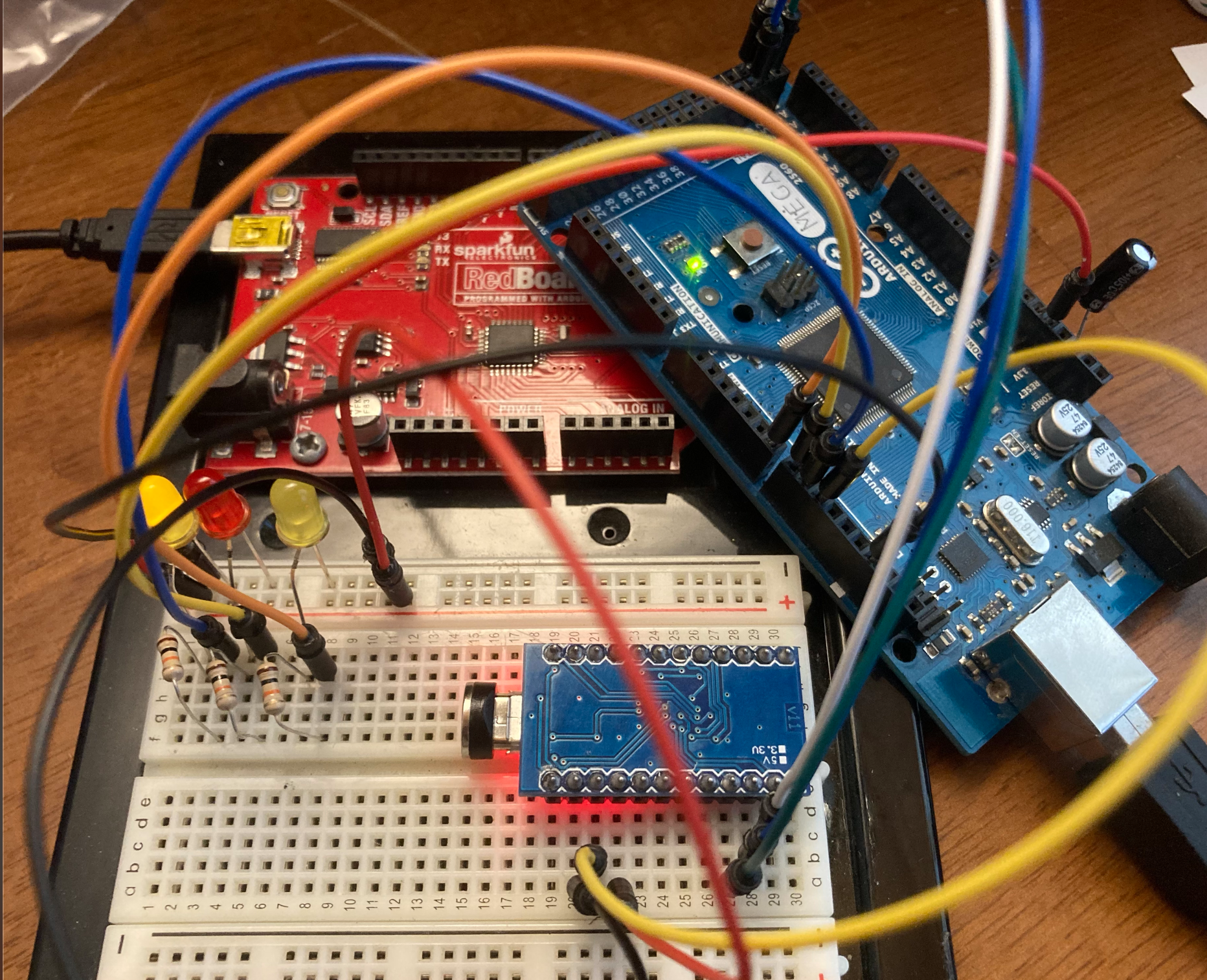
If using Arduino Mega 2560 as programmer
Wiring Arduino Mega 2560 as ISP programmer, to Pro Micro as target:
mega +5V <> promicro VCC
mega GND <> promicro GND
mega 50 (MISO) <> promicro 14 (MISO)
mega 51 (MOSI) <> promicro 16 (MOSI)
mega 52 (SCK) <> promicro 15 (SCLK)
mega 53 (SS) <> promicro RST
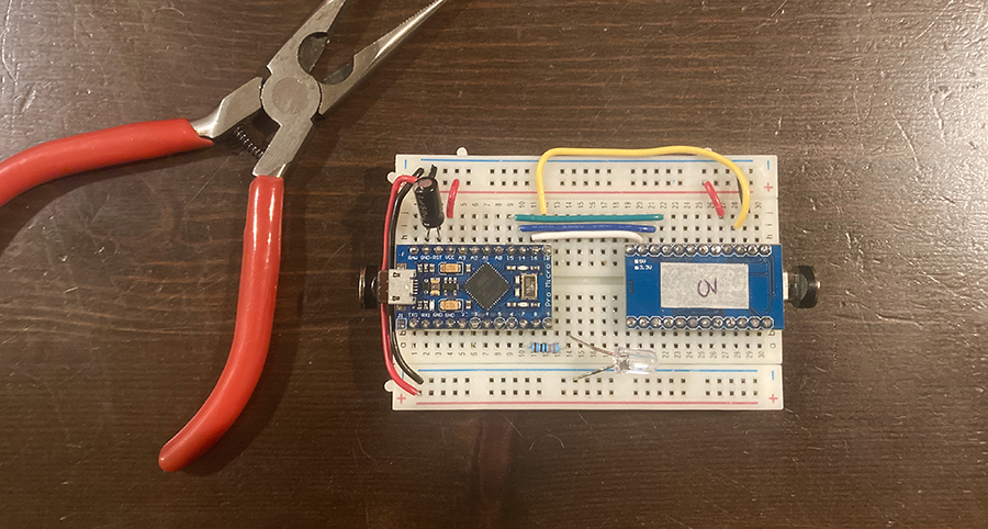
If using Pro Micro as programmer
You can also use a spare Pro Micro as the ISP programmer for a target Pro Micro. I ended up wiring this into a breadboard later after acquiring spares, because it made my ISP setup significantly less bulky than the Mega2560 with all the jumper cables.
There are two things you need to change before setup to make this work.
1. Add promicroisp settings to your Arduino application.
Locate your Arduino application settings. On OSX 10.14, I found them in /Applications/Arduino.app/Contents/Java/.
Within that folder, add the following to hardware/arduino/avr/programmers.txt.
promicroisp.name=Pro Micro as ISP
promicroisp.communication=serial
promicroisp.protocol=arduino
promicroisp.speed=19200
promicroisp.program.protocol=arduino
promicroisp.program.speed=19200
promicroisp.program.tool=avrdude
promicroisp.program.extra_params=-P{serial.port} -b{program.speed}
Thanks to the Arduino forum and Arduino GH issue #1182 for documenting this.
2. Change the RESET pin in the ArduinoISP sketch
In the ArduinoISP sketch, find the line that says:
#define RESET SS
and change it to:
#define RESET 10
Also from the Arduino forum.
You can then follow the same ArduinoISP setup instructions as previously linked.
Wiring Pro Micro to Pro Micro
Since they’re both Pro Micros, the wiring is 1:1 except for the reset pin; wire pin 10 on the ArduinoISP to the target board’s RST pin.
promicroISP +5V <> promicro VCC
promicroISP GND <> promicro GND
promicroISP 14 (MISO) <> promicro 14 (MISO)
promicroISP 16 (MOSI) <> promicro 16 (MOSI)
promicroISP 15 (SCK) <> promicro 15 (SCLK)
promicroISP 10 (RST) <> promicro RST
It’s avrdude time
Identify your port
I did ls /dev/cu* before and after plugging in the USB to check my port name. Mine ended up being either /dev/cu.usbmodem14101 or /dev/cu.usbmodem14201, but yours may differ.
Sanity check that the devices are talking
Sanity check that you can talk to your board with avrdude -c <programmer type> -P <USB port name> -p <target board name>. You also might need to set your baud rate with -b. My output ended up looking like this:
$ avrdude -c arduino -P /dev/cu.usbmodem14101 -p ATmega32u4 -b 19200

avrdude: AVR device initialized and ready to accept instructions

Reading | ################################################## | 100% 0.01s

avrdude: Device signature = 0x1e9587 (probably m32u4)

avrdude: safemode: Fuses OK (E:CB, H:D8, L:FF)

avrdude done.  Thank you.
Are your fuse bits correct?
If you are changing bootloaders, you will need to change the fuses too. If not, you can ignore this section.
Fuse bits are stored configuration bits for AVR microcontrollers which control low-level settings, such as the internal oscillator multiplier. See AVR fuse bits explained - Hackaday.
You can permanently brick a board by setting the fuse bits incorrectly, so make absolutely sure you have picked the correct bits before doing this, and then triple check that they are typed correctly. I got the appropriate fuse bits from this section of the QMK ISP flashing guide.
For a DFU bootloader on a 5V 16MHz atmega32u4, I added -U lfuse:w:0x5E:m -U hfuse:w:0x99:m -U efuse:w:0xC3:m to my avrdude command. Again, these are not going to be the same for some other combination of bootloader and chip, so please triple check that you have the correct ones for your hardware & firmware.
Final flashing process
In summary, to fix the messed up bootloader on my 5V 16MHz atmega32u4 using an Arduino as an ISP programmer, and replace it with a DFU bootloader, I did this. (Do NOT copy these exact commands for any other combination of chips/bootloaders – you will probably brick your hardware.)
- Sanity check that the right flags are being passed and the board is responsive.
avrdude -c arduino -P /dev/cu.usbmodem14101 -p ATmega32u4 -b 19200This should list a nonzero device signature and say something like “Fuses OK”.
- Set the correct fuse bits for a DFU bootloader on this chip. (ONLY IF SWITCHING BOOTLOADER)
avrdude -c arduino -P /dev/cu.usbmodem14101 -p ATmega32u4 -b 19200 -v -e -U lfuse:w:0x5E:m -U hfuse:w:0x99:m -U efuse:w:0xC3:m - Flash production-ready
.hexfile of choice, e.g. firmware containing a bootloader.avrdude -c arduino -P /dev/cu.usbmodem14101 -p ATmega32u4 -b 19200 -v -e -U flash:w:bootloader_atmega32u4_1.0.0.hex
At this point, you should be able to flash with qmk again.
Conclusion
I learned a lot about AVR programming during this process; mostly that I find it unbelievably stressful and despairing. My sincerest hope is that this blog post will save you from days of sobbing into your firmware toolchain like I did. Good luck!