R61 trackpoint keyboard mod, Part 1
The Lenovo trackpoint has historically been my most beloved single ergonomic peripheral for a long time. I have sorely missed the trackpoint since I switched over to OSX in order to simultaneously meet my coding and photo/art/video needs without dual-booting or VM frustrations, even though Apple makes the most painful keyboards ever to grace a laptop.
As much as I enjoy Lenovo’s original pillowy key travel, my worst RSI issue is that my pinky pain flares up pretty bad on a standard keyboard arrangement, which means it’s no longer a sustainable option to just use external Lenovo keyboards. So I’m going for the dream setup: modding a Lenovo trackpoint module onto an ergonomic keyboard.
I got a lot of help for this build from manna_harbour’s doc on building a qmk trackpoint hotswap. Though an excellent resource, it is lacking in visuals, so I took plenty of photos to make a more detailed build writeup – hope that will clarify some of the things I had to piece together.
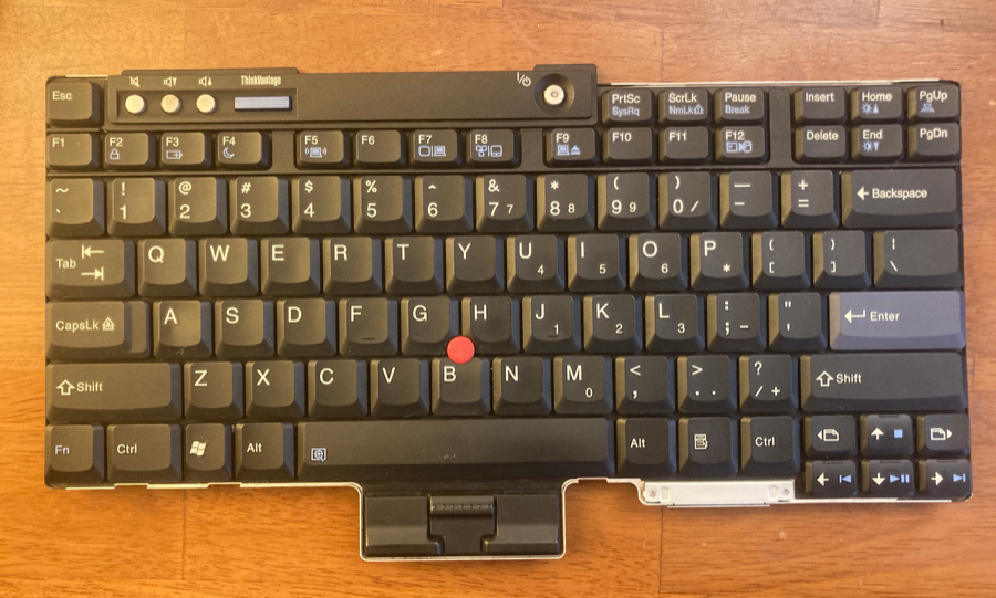
1. Acquire a Lenovo trackpoint module
The trackpoint module is not sold standalone; you have to acquire an entire Lenovo keyboard. If you don’t have access to a supply of scrapped computer parts, the replacement keyboard fortunately isn’t too expensive on Aliexpress.
Because my keyboard is a crkbd, I’m working with a free space a little longer than the footprint of a Pro Micro. This means I need an R61 module, which can be disassembled in half without precision surgery.
The particular trackpoint module will not be searchable or guaranteed from the keyboard’s appearance, so you will need to get the keyboard’s part number from the seller and check against a list of known versions containing the module you want. I ended up getting a 39T0988 for $16 including overseas shipping, and then waited a month or so.
Other part numbers verified to contain an R61 module include 39T7148 and 42T3241.
Get the module out of the keyboard
You’ll need a very small (#00) Phillips head screwdriver.
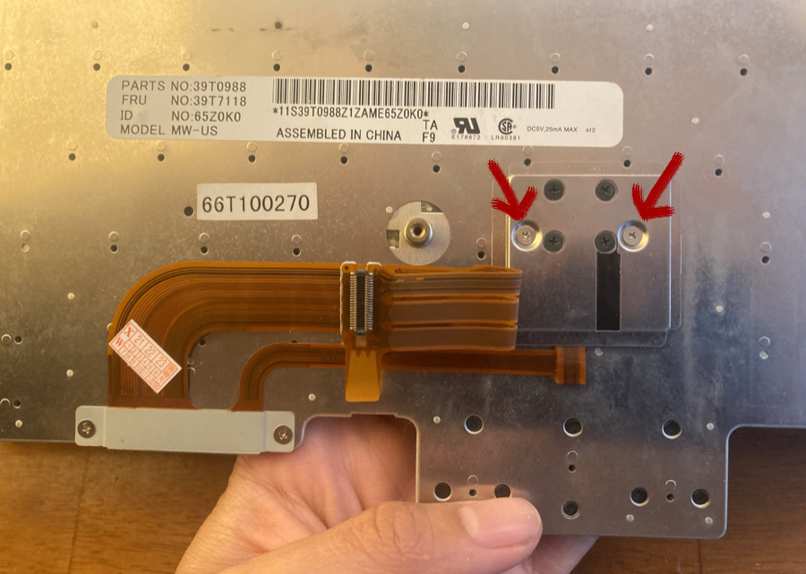
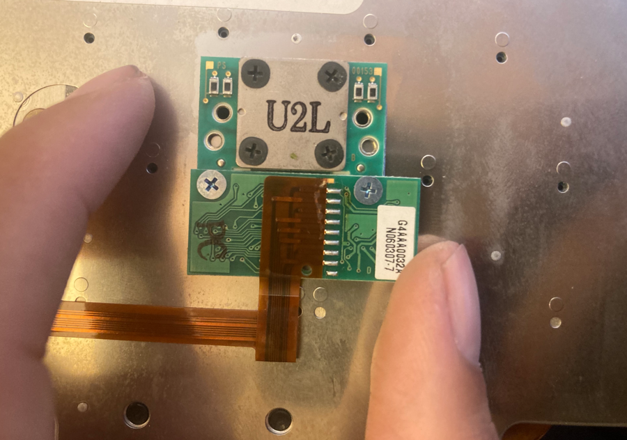
Remove the two silver screws (not the set of four smaller black screws) on the back which hold down the module cover.
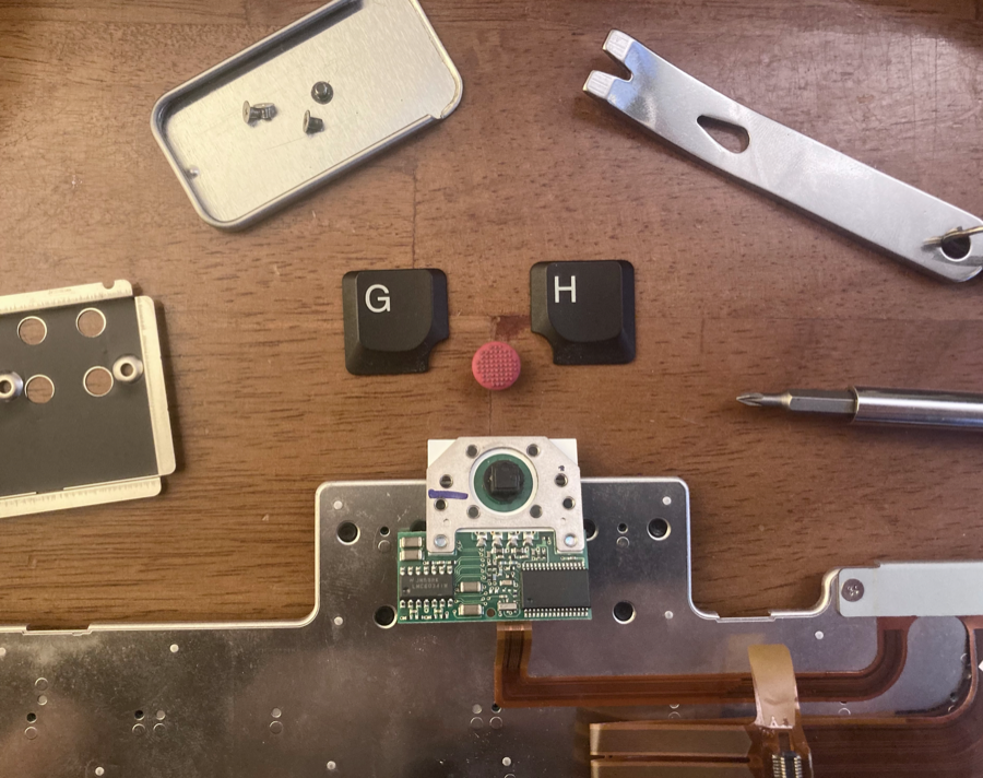
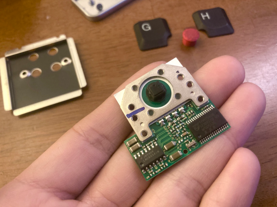
Remove the red trackpoint cover (for safekeeping), and the two screws beneath the G and H keys.
Here’s what the back of the module looks like under the cover.
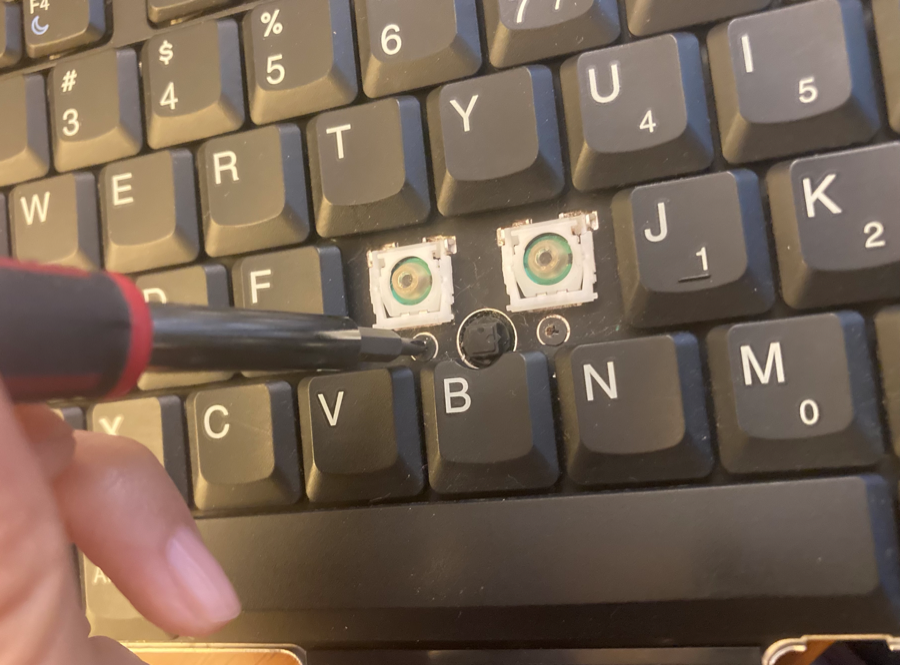
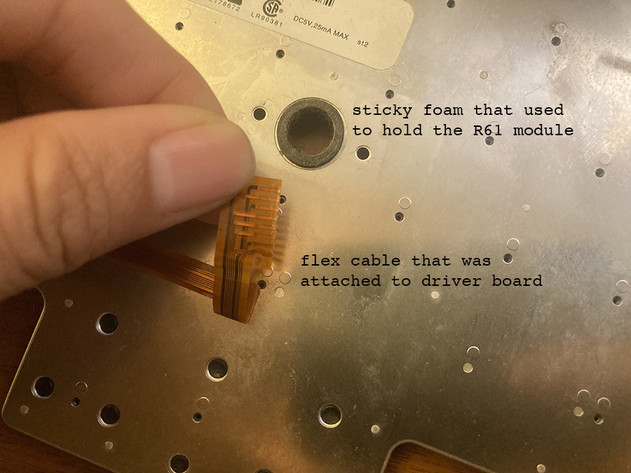
There will be an extremely sticky piece of round foam seated around the trackpoint that is still holding the module in place. Push down hard on the trackpoint from the top and pry/wiggle the board from the bottom. It might take a scary amount of force to get it out; just make sure to apply force evenly and from the center so you aren’t stressing the board.
Break the yellowish flex cable off the board by stressing the joint back and forth a few times. This won’t hurt the board, just the cable (which you won’t need any more).
2. Reassemble R61 into smaller footprint
This section only applies if you have an R61 module that you want to squeeze into the footprint of a Pro Micro. If you have enough room for the entire thing on your keyboard, you can skip this.
Tools
- whatever you need to safely solder in a ventilated area
- something to strip wires with
- desoldering braid
- helping hands and needlenose pliers are very helpful
While soldering, I prefer to wear a mask and have a fan blowing air away from me, but angled so as not to blow my delicate components all over the place. If your mouth feels weirdly dry, then you have definitely been inhaling too many solder fumes and you should take a break and ventilate your space better. It’s really nasty stuff.
Materials
- 2” of ribbon cable, 4 wires wide
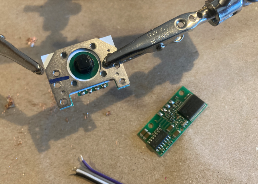
Separate the driver & sensor boards
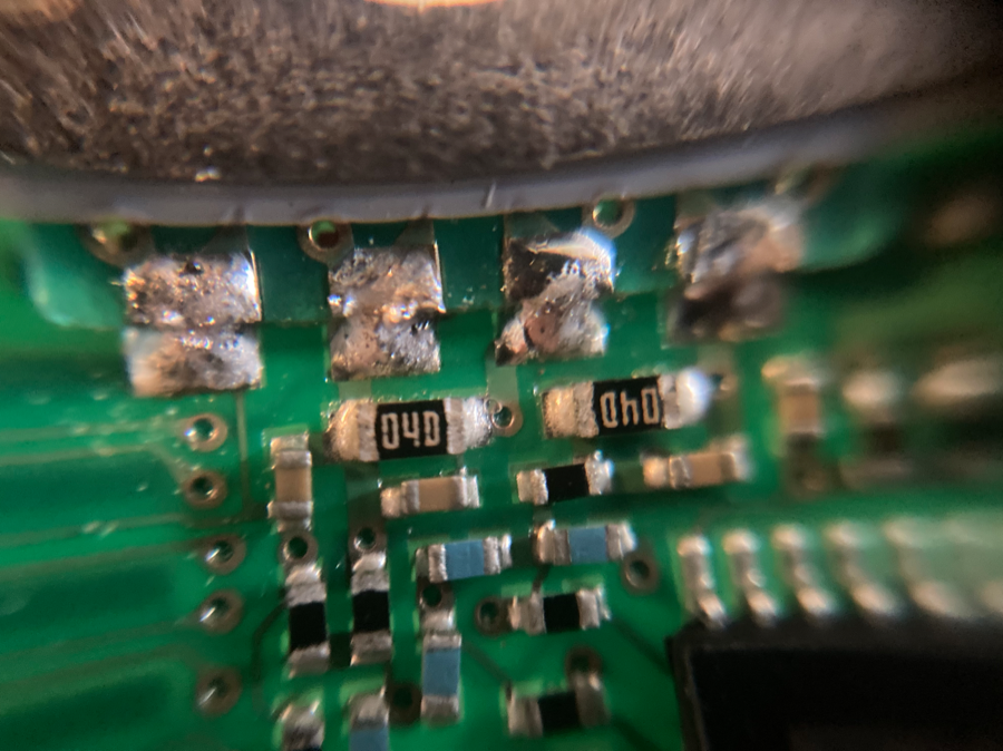
Remove the two screws joining the trackpoint and driver board. They will still be held together by 4 solder joints, which you’ll want to desolder.
Be very careful not to accidentally desolder the tiny SMCs right next to these pads, or to desolder the pads themselves. I accidentally did that once to another device that was time-consuming to source, and it was incredibly nervewracking to deal with. Don’t work on the same pad too long, keep moving, and give them lots of cooldown breaks. If the ICs feel warm, the board needs a break.
This was about as far as I felt I could safely get with desoldering braid (there wasn’t a lot of room to maneuver).
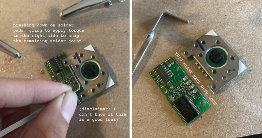
Once I didn’t feel like I was making any more progress, I carefully scored the joints with a razor and then found an object that was the right size to evenly apply pressure across all of the lower pads (a lockpicking torque wrench works great). I wanted to reduce any strain that risked ripping up the stressed pads while I very carefully snapped through the remaining joints by torquing the boards.
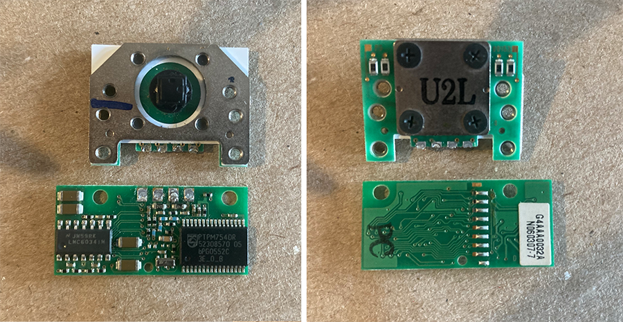
Reference photos of the original orientation.
Re-connect the sensor and driver board in new arrangement
I decided to keep the driver board facing in its original up-orientation so that the pinout would face downward.
Re-tin the desoldered pads with blobs of solder. This will make it easy to heat the pads and quickly push the wires into place.
I had to hand strip these wires with my cutters, which is always tricky. I found it was easiest to bend the ribbon cable coming off the trackpoint at a right angle before soldering to the driver board.
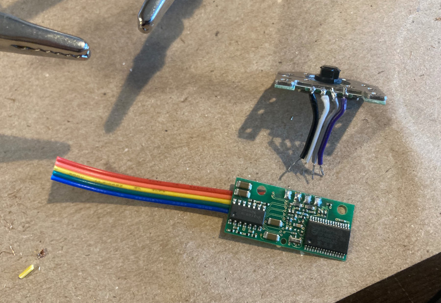
We’ll talk about the rainbow cable coming off the bottom of the driver board in the next section. I just decided it would be easier to solder it on before reconnecting the trackpoint and driver.
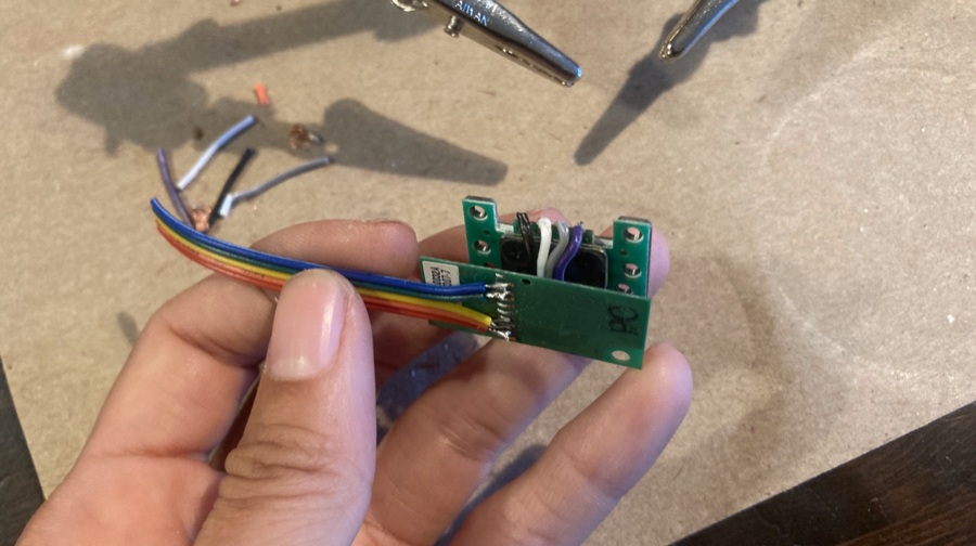
3. Driver board connection
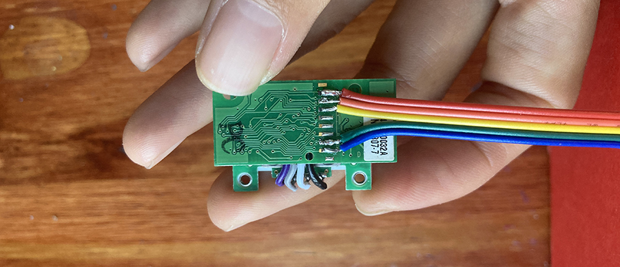
Solder ribbon cable to output pins
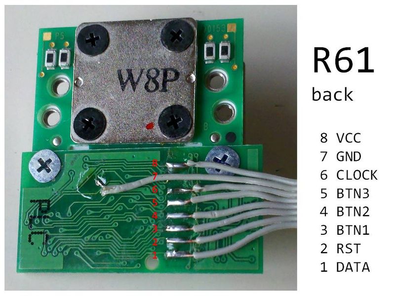
pinout photo from Deskthority -- not sure what they're doing with the GND pin, maybe they accidentally desoldered pad 7.
Note that we no longer have the button hardware, so you can ignore pins 3, 4, 5. Triple check the orientation of your board relative to the pinout diagram. Then, solder a 5-wire ribbon cable to pins 8 (VCC), 7 (GND), 6 (CLOCK), 2 (RESET), and 1 (DATA). I used the traditional red wire for VCC.
Blockers to continuing
I’d like to wait to reflash QMK until I can get hold of compatible machine pin headers to solder into spare Pro Micros, to avoid keyboard downtime in case I run into any more firmware shenanigans.
Pro Micros are extremely inexpensive compared to the cost of cumulative nerve damage – my stabbing pinky pain flared up again when my keyboard was last out of commission – so I’d like to have a pair of spare working controllers at all times after dealing with that firmware debacle.
Hope to finish up this project soon!